RVSAT-1: A Microbiological Experiment in Space
Published: 2025-02-03
RVSAT-1 is a 2U cubesat entirely designed and developed by Team Antariksh — an interdisciplinary team of passionate undergraduates from R V College of Engineering. I had the fortune to be a part of this team in college. This post outlines some of the work that we’ve done as a part of this project.
Our Objective
The mission of RVSAT-1 was to study the growth rate of Bacteroides thetaiotaomicron (B. theta) in space and compare that to its growth rate on Earth. B. theta is a bacterium prominent in the human gut microbiome and plays a role in the human digestive system. Study of B. theta in microgravity can help future human missions to space. We used Optical Density as a proxy measure for microbe concentration in the medium.
Experimental Setup
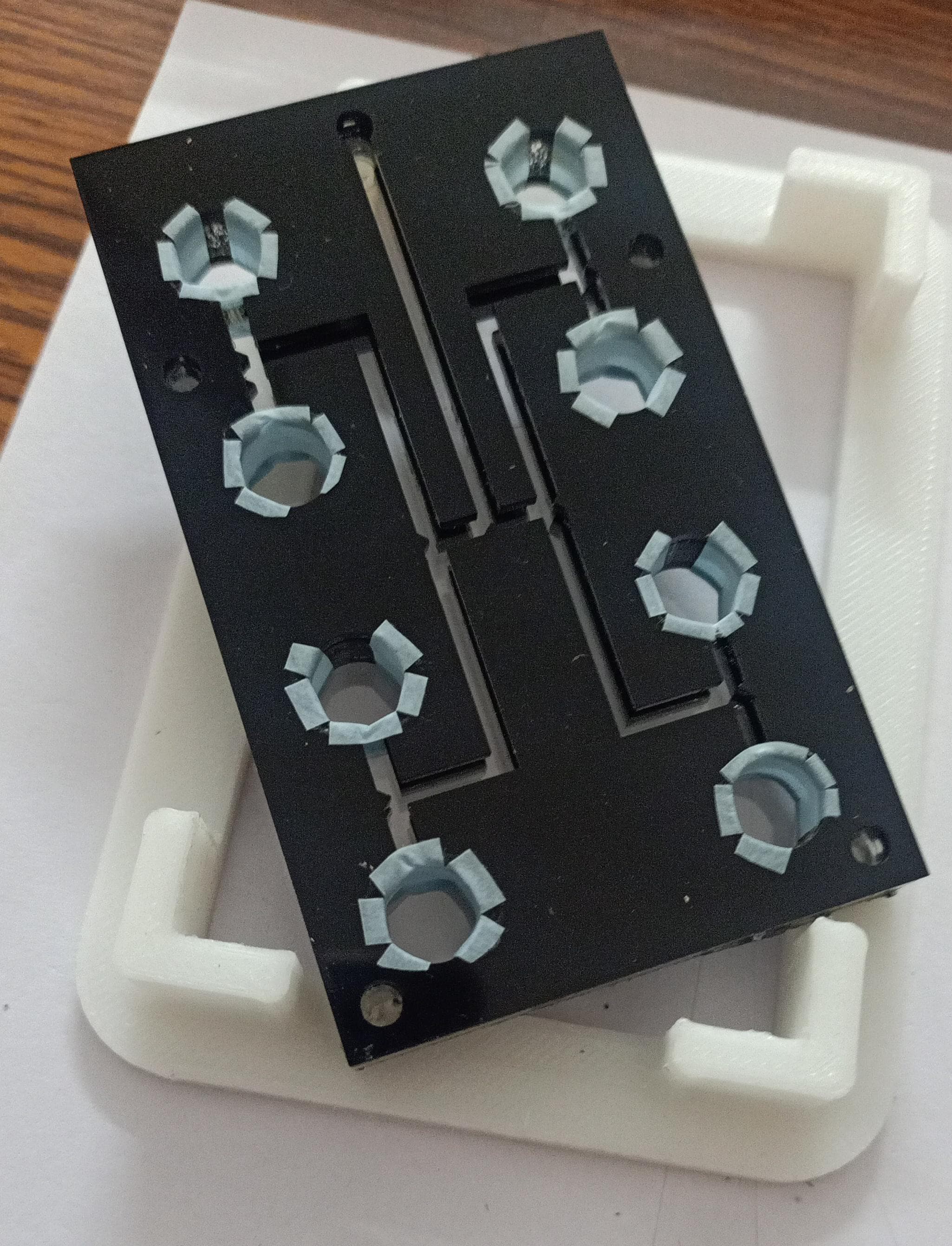
Our experiment was conducted in a MicroFluidics Card (MF Card). The MF card contains 8 microwells within which the microbes are stored in a lyophilized (freeze dried) form. The card also has tiny channels through which the liquid growth medium flows into the wells once the experiment starts. The MF card was designed in-house and manufactured from Poly Methyl MethAcrylate (PMMA).

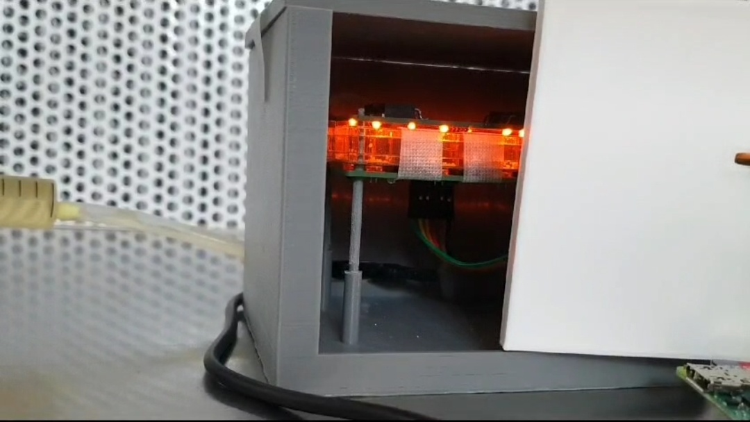
The microwells are transparent on the circular faces of the cylinder. Each microwell has a photodiode on one side and an LED on the other side. To measure the Optical Density, we turn the LEDs on, and measure the amount of light that passes through the medium to fall on the photodiode on the other side. The photodiode outputs current which is fed into a transimpedance amplifier to convert it into a voltage. This voltage is read by the Flight Computer through a 12-bit Analog to Digital Converter (ADC).

This setup is inexpensive and lightweight, making it optimal for use within a cubesat.
Temperature Control
There is a significant temperature fluctuation in orbit based on whether the satellite is facing the sun, or hidden from it in Earth’s shadow. However, B. theta requires an optimal temperature of 37°C. The whole payload is wrapped in Multi-Layer Insulation (MLI) to minimize thermal fluctuations. But for precise control, we implemented an Active Thermal Control (ATC) system.
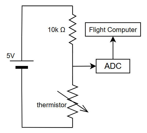
The microfluidics card contains two small grooves within which two thermistors (temperature dependent resistors) sit. Each thermistor is in a voltage divider circuit with a 10k resistor. The voltage between the two resistors is read by the Flight Computer through a 12-bit ADC. From this voltage, it is possible to calculate the resistance of the thermistor. There is a non-linear relation between the resistance of the thermistor and its temperature. Using this relation, it is possible to deduce the temperature of the MF card.

We used two custom-made 12V Kapton heaters to regulate the temperature. The heaters are powered through a MOSFET and controlled by the Flight Computer using Pulse Width Modulation (PWM). The flight computer runs a PID loop for temperature, which reduces oscillations while also ensuring fast convergence.
Flight Computer
We used a Raspberry Pi Zero 2 w as the main Flight Computer for this mission. RPi is a cheap computer that usually runs a Linux based Operating System. Typically, cubesats use microcontrollers as their Flight Computer. However, we went with an RPi since it can run programs in any language and therefore speeds up development time. This was important to us as we were on a tight timeline throughout the project.

We designed a hat for the Pi that includes a few MOSFETs for controlling the fluidic valve and the heaters. The hat also makes it convenient for interconnection with other PCBs like the communications board or the Electrical Power System.
Communications PCB
We built a separate board to handle communications with the POEM Platform. POEM - 4 platform communicates over an RS485 bus at 2Mbps. We used a MAX3443 IC to act as a transceiver between UART and RS485. The POEM platform communicates using 9-bit RS485, where the 9th bit acts as a mod bit — it determines whether the sender of the byte is the POEM platform or a payload. Since the RPi zero 2 doesn’t support 9 bit UART, we used an STM32 to act as a middleman between the Pi and the platform. Whenever our payload is polled by the platform, the comms PCB responds with two bytes of data. A buffer of two bytes is implemented on the STM32 to avoid the latency of getting the data from the RPi when it is polled. After responding to the platform, the communications PCB pings the Flight Computer for the next two bytes.
Electrical Power System
Since we launched on the POEM platform, we did not need to generate our own power. PS-4 stage of the PSLV provided us with raw power at around 30V. In our payload, we needed a 12V line for our heaters and valve, a 5V line for the RPi and many ICs, and a 3.3V line for the STM32. We used a buck converter circuit to convert the raw power into the three regulated lines. One buck converter first brings the raw power to 12V. Two other buck converters take this 12V as input and give 5V and 3.3V lines as output respectively. The PCB that houses this circuitry is called the Electrical Power System (EPS).
Software
The bulk of the software is written in python and runs on the RPi zero. This is one of the main reasons why we chose an RPi in the first place. The program runs two threads: one running the main loop and another one that handles only comms. The main loop includes fluid inoculation, temperature control, LED control and light intensity measurement. The comms thread is responsible for responding to the pings from the Communications PCB. The two threads share a byte array — the main thread writes to it and the comms thread reads from it. We segment the data into 32-byte frames before transmission, which aids in decoding the data once it is received on Earth. A systemd service is created to run this program on boot.
The small piece of code that handles the logic in the STM32 was written using Embedded C.
A few general tips for similar projects
Working on this project provided valuable lessons that can be applied to other large projects. Some of these are:
Modularity is important
Don’t design one PCB with another PCB in mind. For example, your Electrical Power System (EPS) should not be designed with the exact number of output lines as required. Instead, each PCB should be independent and usable on its own. This way, when requirements change, you won’t need to redesign every PCB.
This principle also applies to software development. Avoid writing functions or designing classes with a specific caller or user in mind. Instead, ensure that each function and class is self-contained and independently usable.
Modularity helps manage change more effectively. It also makes it easy for your team to work in parallel.
Debuggability is important
Electronics and code rarely work perfectly on the first try. Including debugging pins on all PCBs will make your life much easier when you need to troubleshoot. If your PCBs are enclosed in a container, try to pull the debugging pins out even if you think you won’t need them — trust me, you’ll thank yourself later.
For example, pulling out the programming pins of the STM32 through the DB-9 connector of the payload allowed us to make last-minute modifications to the code. This saved us lots of time and money. If we had to open and close the payload for changing the code, we would have had to perform one more expensive shock test.
Design repairable PCBs
When designing PCBs, keep repairability in mind. A single IC failure shouldn’t render the whole board useless. Use female headers or sockets for components that are likely to fail. This way, if a component fails, you can just replace it without having to discard the entire PCB. This will save you a lot of time and money during development and testing.